
The Sound of Tubes ?
At TestHiFi we discuss and develop ways to measure aspects of music reproduction. Sometimes, working on my own loudspeaker projects, such aspects draw attention. About such an event I want to write this time.
When I start listening to a new speaker design, during the „rough“ sessions I use a simple chip-based amplifier. It is good enough to show the most important voicing aspects clearly. It also has low output impedance. More about this later. The CDP in use is a similarly revealing CEC TL51XR. Pure solid state sources.
When the speaker seems ready for high quality listening, I change to tube amplification and DACs / CDP. For my ears, these provide even more natural sound. Necessary to check if my speakers reveal this.
But, before that change, I care for mostly linear speaker impedance.
Why care for linear loudspeaker impedance?
First – what is impedance? A loudspeaker presents a load, which is driven by the amplifier output voltage. Depending on it’s impedance, the speaker draws current. According to Ohm’s law I (current) = U (output voltage) / Z (speaker impedance).
Hence, lower impedance draws more current at a given voltage. Most amplifiers are designed as „voltage sources“, they try to produce constant output voltage for constant input. That way, they provide current unimpeded by internal resistance. Nevertheless, most are not perfect at this. Usually, some amplifier output resistance remains.
Together with the load impedance this amplifier output resistance creates a „voltage divider“:
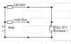
voltage divider
Due to the current demand of the loudspeaker, some voltage doesn’t arrive at the speaker but is lost at the amplifier output resistance. Ohm’s law again: U (loss due to amp out resistance) = I (current demand of speaker) * Z (amplifier output resistance).
In the „test circuit“ shown above, we can connect the speaker to 0.001 or 3 ohms of amplifier output impedance.
Real world loudspeaker impedance
Sometimes people ask me if they may use a nominal xx ohms loudspeaker (manufacturer spec) on an yy ohms amplifier output. Well, besides many manufacturers overstating the impedance, it is also far from being constant.
Let us consider at a typical fluctuation of loudspeaker impedance over frequency:
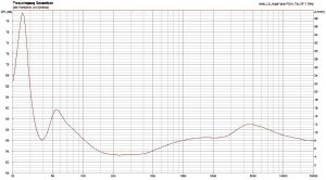
Zimp_TAU2011
The impedance varies between 4-5 ohms in the lower midrange and nearly 40 ohms around 25 Hz.
At those frequencies with high speaker impedance, less current is drawn from the amplifier. Therefore, less output voltage is lost at the amp’s output resistance, the speaker receives more driving voltage. Vice versa, low speaker impedance induces higher amp out voltage loss, lowering speaker drive voltage and SPL output.
All in all, the frequency dependent loudspeaker impedance results into a similar looking SPL variation. Amplifier output resistance (together with terminal and cable resistance) determines how strong the SPL deviations are.
Different amplifiers have different output resistance
Most solid state amplifiers – such as my chipamp – have low output resistance (about 0.1-0.2 ohms or less). But single ended (SE) tube amplifiers without feedback from the output stage have higher output resistance. Let us assume a not unreasonable 3 ohms for a simulation of the effect on loudspeaker SPL.
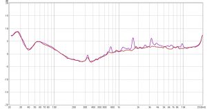
The following picture shows the simulated difference between the chipamp driving an (assumed perfectly linear) loudspeaker, compared to our 3 ohms SE tube amp:
SPL_Variation_due_to_LS_Z
SPL varies between 92.5 and 89 dB due to loudspeaker impedance variation. Speaker impedance shown again to indicate correlation.
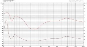
Now for a real world example, with even higher output resistance, measured at the listening position. I divided the measured SPL response with the SE tube amp by the same using a chipamp, to show the difference. Left and right channel results shown:
SPL_variation_at_listening_Pos
The speaker used is the same as simulated above. Therefore, the SE tube amp’s output impedance has similar influence on SPL vs frequency
Now, why so much fuss about those SPL variations?
Now about my listening experiment.
I dedicated a lot of time to improvements of my Betahorns during the last 2 years. With very good results. Due to their higher directivity (which suppresses the influence of some room reflexions) horn systems are very revealing. Honing the SPL response towards neutrality during many voicing (listen and measure) sessions rewards me with exceptional uncolored music reproduction.
Before I decided to turn towards tube amplifiers, I often thought some of their sound’s difference is due to SPL variations. Simply because they produced markedly different tonality. Sometimes I tried to emulate the effect by varying the speaker response, mostly without success. That was more than a decade ago.
Now, as the Beta’s seemed the perfect instrument to explore sounds, I decided to repeat those experiments, focusing on midrange balance.
The tube amp in use is based on a GM70, powerful, with relatively low output impedance (not yet measured).
As measured and simulated above, SE tube amps tend to emphasize the upper end of the midrange (>440 Hz) compared to the fundamentals (150- 440 Hz). The Betahorn has much lower impedance variations, therefore the influence of amplifier output resistance is much lower than in my previous example. Maybe some 1/10 dB of tilt around 440 Hz.
Also, the higher second order harmonic distortion of SE tube amps will additionally add (at 1%) around 1/10 of energy towards higher frequencies. Please see my last blog (Simple Distortion Measurements) for some measurements.
Hence, I decided to subtract 1/10 dB in the 180-400 Hz range and add 2/10 between 500-1500 Hz. Via this crossover modification I tried to balance the midrange reproduced by the chipamp similar to that using the SE tube amp.
The result
Indeed: that modification induced a similar „bloom“ to the midrange using the chipamp as (unmodded) with the SE tube amp! The midrange seemed to sound „enlightened from within“. Not only this, but also phantom images appeared larger. Also, the „hard sounding presence-and-detail“ range (1.5-3kHz) of the chipamp seemed less prominent. Probably due to better „masking“ by the enhanced midrange.
All in all, the mod did not turn the chipamp into the more open, real and dynamic sounding GM70 SE. And the better clarity of timbre of the tube gear also seemed not due to „second order harmonic enhancement“. Otherwise, it would not sound even more superior with more complex sounds than the chipamp. Nevertheless, a good step in exactly that direction! As perceived by me, of course you may judge differently. I decided to integrate this effect as user selectable into the Betahorn crossover.
Final word
As said, I do like my tube amps, DACs and CDPs as the most transparent and lifelike sounding sources. But when comparing tube and solid state amplifiers, we should not forget the influence of their output impedance on the sound of the loudspeakers they drive. Only speakers with purely resistive (frequency independent) impedance will purely show the difference in amplifier sound.
I allowed myself to freely mix „resistance“ and „impedance“, ignoring phase. Sorry. Too „complex“ within the context 😉
Speaker simulations done with the very nice and free “Boxsim” simulation software. Measurements with REW, just as wonderful and free!